GD&T symbols with examples define geometric tolerances — shape, orientation, location, and runout — and show practical callouts (Position, Flatness, Profile, Circularity) that ensure part function.
Ever wondered how 2D drawings and 3D models become parts that fit, seal, and spin correctly?
I teach GD&T symbols with examples, the way I learned on the shop floor: crisp rules, tight sketches, and decisions tied to function.
This guide is for students and practicing engineers who want a practical reference. You will learn what matters, why it matters, and how to apply each symbol today. By the end you will know which callout to use.
What GD&T symbols with examples do and why they matter
Geometric Dimensioning and Tolerancing captures form, orientation, location, and runout. It replaces ambiguous dimensions with functional rules. A clear callout tells the shop how a part must behave — not just what size it is. Good GD&T cuts inspection time, removes guesswork, and lets measurement prove function. Before any callout, ask: which mating relationship fails if this feature is off? That question drives the symbol choice.
Core symbols
• ⌀ Diameter — hole for dowel or shaft.
• ⌖ Datum — primary reference face for location.
• Position (⦿) — use Position for bolt circles and locating patterns.
• Flatness — control mounting faces so assemblies do not need shims.
• Profile — use Profile for sculpted or sealing surfaces.
• Circularity — control journal roundness to protect bearings.
• Runout / Total Runout — control rotating surfaces for balance.
How to choose a symbol — the functional rule
Choose the control that directly prevents failure. If a hole is located, use Position. If a face mates and seals, use Flatness or Profile. If rotation must be vibration-free, use Circularity or Runout. This practical filter beats textbook trivia.
Detailed examples — short case studies
Flange bolt pattern — Position
Boltholes drifted after welding. I specified Position to datum A (mating face) and datum B (centerline) with MMC. The shop used bonus tolerance while assembly fit was guaranteed. Result: first-pass assemblies replaced rework cycles.
Motor mounting face — Flatness
Motors tipped and required shims. A single Flatness callout on the machined face allowed one-setup machining and removed routine shimming.
High-speed shaft — Circularity and Runout
Out-of-round journals caused bearing failures. Adding Circularity and measuring Runout on finished shafts reduced vibration and extended bearing life.
Linking tolerance stackup to GD&T
Convert chains of linear dimensions into geometric controls when assembly performance depends on geometry. A tolerance stackup analysis tells you if size tolerances or a Position control better meets assembly needs. Geometric controls often reduce worst-case accumulation and clarify inspection.
Practical comparison table
| Method | Best use | Trade-off |
| Chain dims | Simple linear fits | Cumulative error |
| Position | Locating features | Requires datum planning |
| Profile | Mating complex surfaces | More inspection work |
Teach-a-junior checklist
- Identify function: locate, seal, or rotate.
- Pick the primary Datum where the assembly mates.
- Use Position for bolt patterns; add MMC for fit.
- Use Flatness to eliminate shimming.
- Use Profile for complex sealing surfaces.
- Tie each callout to a measurement method: CMM, plug gage, profilometer.
- Avoid redundant dimensions that contradict a geometric control.
- Note a short inspection routine on the revision block.
Measurement mapping — inspection made repeatable
For every GD&T callout, add one inspection note: the tool and the step. Example: Position → CMM, measure hole center relative to datum feature A, compute virtual condition per MMC. If you use Profile, add scanning strategy and acceptable deviation. This keeps inspectors and designers aligned.
How to draw GD&T symbols with examples on a production drawing — step by step
- Start with a function: mark which surface controls sealing, alignment, or motion.
- Select the primary Datum where the assembly contacts the part; mark it with ⌖ and a sketch.
- Choose the symbol that prevents the failure mode: Position, Flatness, Profile, Circularity, or Runout.
- Add material condition modifiers (MMC/LMC) only when needed.
- Tie the callout to the measurement method (CMM, gage, profilometer).
- Avoid stacked dimensions that force a long tolerance stackup unless justified.
Measuring examples — tools and routines
CMM: Measure datums first, then feature centers. Use best-fit only when permitted. Include the CMM calibration checklist on the route card.
Plug gages: Rapid go/no-go checks for datum fits.
Profilometers: When calling Profile or specifying a surface roughness chart, record sampling length and Ra/Rz values.
Process-aware tolerancing — machining and assembly
Match tolerances to capability. Check speeds and feeds, tooling, and fixture before forcing tight form controls. For sheet parts, plan bend allowance and fixture design before profile tolerancing. For motion systems, account for ball screw selection and bearing preload when specifying positional and runout tolerances.
Welding and fixture notes — control before parts leave the shop
Welds distort geometry. Use welding distortion control techniques — tack sequence, symmetric welds, and fixtures that lock critical datums. Good fixture design reduces the need for tight post-weld controls.
Design for inspection and assembly — (two questions)
1. Design for inspection: can an inspector measure the callout quickly and repeatedly?
If not, change the callout or add a functional gauge.
2. Design for assembly: does the callout guarantee mating without shimming?
If not, consider MMC or a different control.
Engineer’s checklist before release
- Did I pick datums that match real assembly contacts?
- Is each GD&T callout tied to function?
- Can my shop measure this with existing equipment?
- Have I minimized ambiguous notes and excessive Profile use?
Final step — one change to make today
On your next drawing, pick one recurring assembly problem. Replace stacked dims with a single clear GD&T symbol with example, add a tiny sketch, and note the inspection method referencing the CMM calibration checklist. Try it on one part and record the first-article change.
Conclusion
I teach engineers to use GD&T symbols with examples so drawings stop guessing and start proving function. Small, deliberate callouts and a linked inspection plan cut rework and shorten launches. Want templates, diagrams, and a downloadable symbols PDF for shop training?
GaugeHow provides workshop-ready guides and downloadable templates to speed your team. Download the PDF and train your team today now.
FAQs
1. What are the most used GD&T symbols and when should I apply them?
Use Datum, Position, Flatness, Profile, Circularity, and Runout. Apply the one that directly prevents the assembly failure mode.
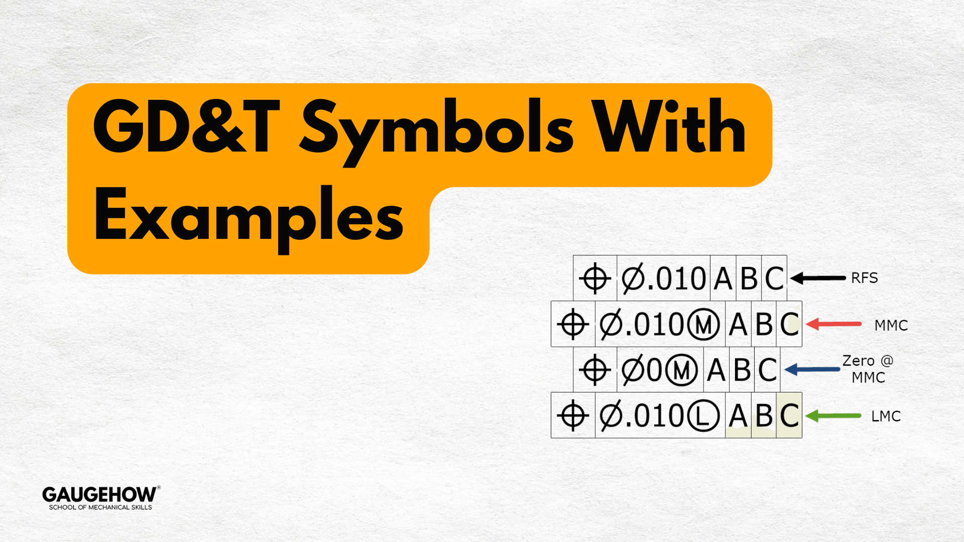
2. How does MMC work with Position?
MMC gives bonus tolerance as the feature departs from maximum material condition. Use MMC to guarantee assembly fit while allowing manufacturing bonus tolerance.
3. Can I measure all GD&T callouts on a CMM?
Most geometric callouts are measurable on a CMM. Specify measurement strategy and confirm the lab follows the CMM calibration checklist.
4. When should I use Profile vs. multiple linear dimensions?
Use Profile when the mating surface geometry matters as a whole. Use linear dims when function or manufacturing constraints make them adequate.
5. How do I keep GD&T simple for the shop?
Pick functional datums, sketch datum features, tie each callout to a measurement method, and avoid redundant or decorative callouts.
6. Can GD&T reduce production cost? Yes. Well-chosen GD&T symbols with examples reduce rework, speed inspections, and lower scrap — treating tolerances as cost levers.